Cisco CCNA VLAN and STP
When Cisco’s talking about switching, they really mean layer-2 switching unless they say otherwise.
Layer-2 switching is the process of using the hardware address of devices on a LAN to segment a network.
How do we break up broadcast domains in a pure switched internetwork?
By creating a virtual local area network (VLAN), that’s how!
A VLAN is a logical grouping of network users and resources connected to administratively defined ports on a switch.
When you create VLANs, you are given the ability to create smaller broadcast domains within a layer-2 switched internetwork by assigning different ports on the switch to different subnetworks.
A VLAN is treated like its own subnet or broadcast domain, which means that frames broadcasted onto the network are only switched between the ports logically grouped within the same VLAN.
Cisco CCNA Before VLAN’s
How do we break up broadcast domains in a pure switched internetwork?
By creating a Virtual Local Area Network (VLAN), that’s how! A VLAN is a logical grouping of network users and resources connected to administratively defined ports on a switch.
When you create VLANs, you are given the ability to create smaller broadcast domains within a layer-2 switched internetwork by assigning different ports on the switch to different subnetworks.
A VLAN is treated like its own subnet or broadcast domain, which means that frames broadcasted onto the network are only switched between the ports logically grouped within the same VLAN.
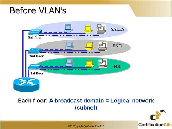
Before VLAN’s, we had hubs for each floor connected to a router, which broke broadcast domains for each floor.
This topology is known as a ‘collapsed backbone’. Not a great solution for larger offices with lots of users. Shared bandwidth via hubs cause collisions on an ethernet network reducing throughput.
Look on the next slide to see a better implementation utilizing switches along with VLANs.
Cisco CCNA After VLANs
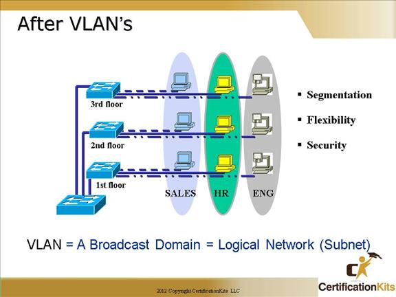
VLAN’s break up collisions domains for each port on the switch.
However, the benefit of the design in this slide is that you are no longer stuck with physical constraints.
You can assign any switch port to any VLAN, so it doesn’t matter where the employee is physically located. Use of switches also break up the collision domain.
Cisco CCNA Benifits of VLANs
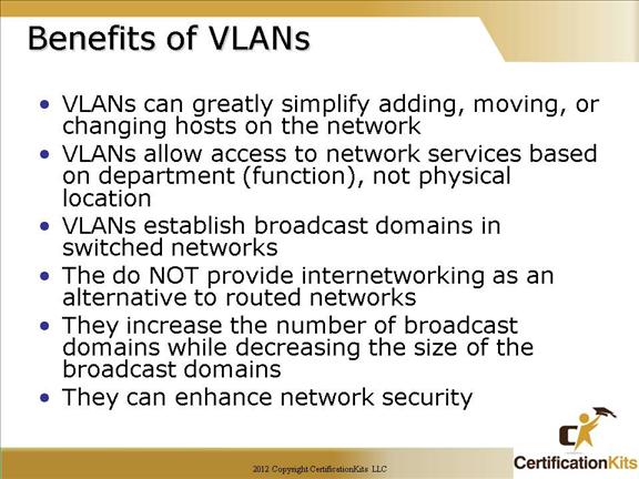
VLANs logically divide a switch into multiple, independent switches at layer 2
A VLAN can span multiple switches
VLANs increase the number of broadcast domains (while decreasing the size of each broadcast domain)
Trunk links can carry traffic for multiple VLANs
Access links carry information about only one VLAN
Cisco CCNA VLAN Operations
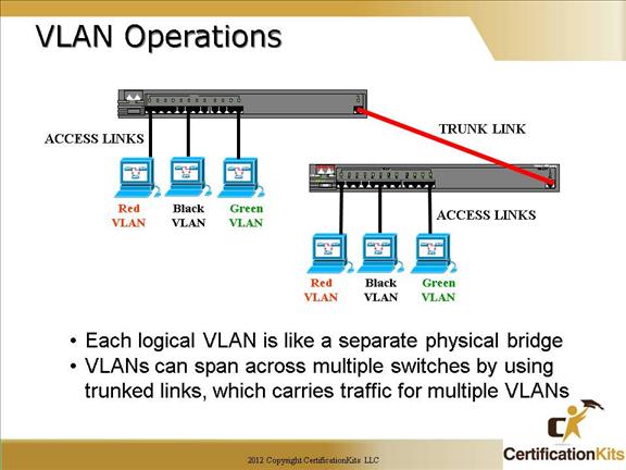
Access links
This type of link is only part of one VLAN, and it’s referred to as the native VLAN of the port. Any device attached to an access link is unaware of a VLAN membership—the device just assumes it’s part of a broadcast domain, but it has no understanding of the physical network.
Switches remove any VLAN information from the frame before it’s sent to an access-link device. Access-link devices cannot communicate with devices outside their VLAN unless the packet is routed through a router.
Trunk links
Trunks can carry multiple VLANs and originally gained their name after the telephone system trunks that carry multiple telephone conversations.
A trunk link can be a 100Mbps or higher point-to-point link between two switches, between a switch and router, or between a switch and server. These carry the traffic of multiple VLANs—from 1 to 4095 at a time.
Cisco CCNA VLAN Operations
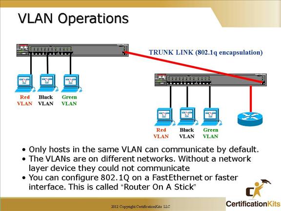
Another benefit to trunking is when you’re connecting switches.
Trunk links can carry some or all VLAN information across the link, but if the links between your switches aren’t trunked, then only one VLAN will be switched across the link.
By default, all VLANs are configured on a trunked links. Specific VLANs that are not required to be trunked across a link can be disallowed by excluding the respective VLANs.
Cisco CCNA 802.1q Frame Tagging
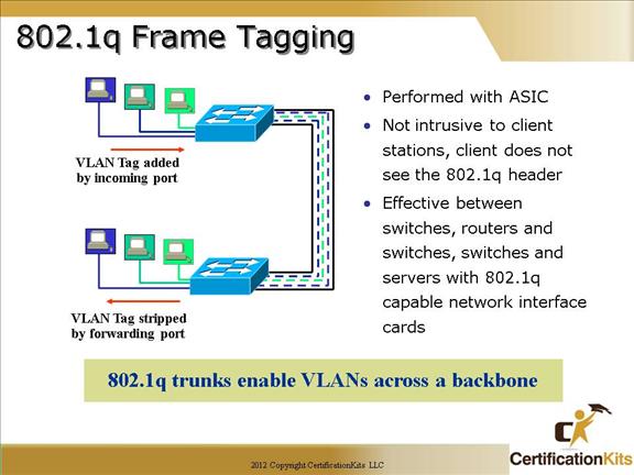
Cisco Catalyst switches use frame tagging with VLAN ID to identify the VLAN membership of a frame over trunked links.
802.1q (DOT1q) inserts a four-byte tag field into the original ethernet frame.
A unique identifier is placed in the header of each frame as it is forwarded between switches. The four-byte tag is stripped off by the switch prior to sending a packet to a host across a not trunk link.
Cisco CCNA Dividing a Physical Interface into Subinterfaces
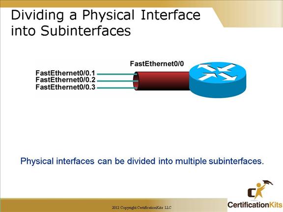
At this point, it is important to understand that if the you want a router to connect multiple VLANs, the router needs a separate connection for each VLAN. The terminology “separate” can be accomplished multiple ways on a router. You can establish a separate physical connection for each VLAN that will interconnect with other VLANs, or you can split a FastEthernet or higher bandwidth interface into multiple, logical subinterfaces as depicted in the figure on the slide.
Cisco CCNA Router Subinterface Example
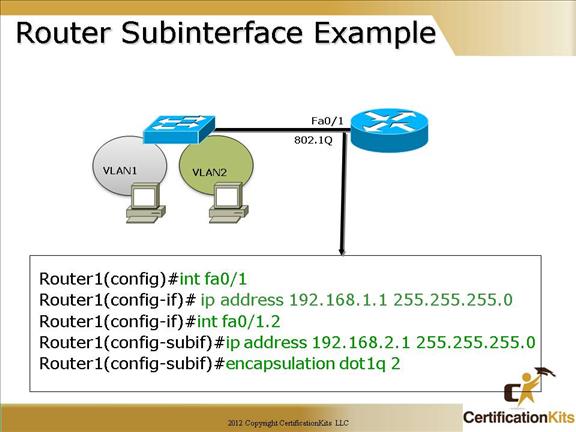
802.1q encapsulation is configured utilizing the “encapsulation dot1q #” command where “#” is the VLAN number.
The example configured on the slide also called ‘router on a stick’. This configuration is not used as frequently now that port densities have increased on the newer devices, hence eliminating the need for sub-interfaces on higher port density devices.
Cisco CCNA Creating Vlans
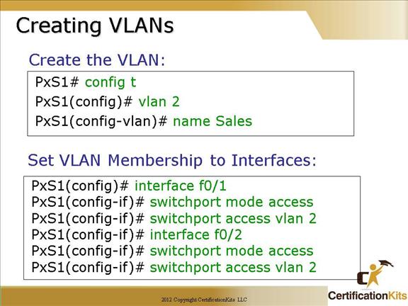
By default a Cisco switch is set to VTP Server mode. In VTP server mode you can add, change or delete VLANs. If you are in VTP Client or Transparent mode then you cannot add, change or delete VLANs. VTP modes will be covered shortly.
The first box shows an example of how to create a VLAN and assign a name to the VLAN.
The second box shows an example of assigning switch interfaces as access ports to the specified VLAN.
Cisco CCNA Creating Trunk Ports
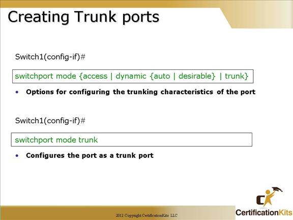
There are four options to the “switchport mode” command. They are as follows:
Trunk – Configures the port as a 802.1Q trunk port.
Access – Disables trunk mode and associated trunk mode negotiation.
Dynamic desirable – Triggers the port to negotiate the link on a nontrunk port to trunk mode.
Dynamic auto – Enables a port to become a trunk only if the connected device has the state set to trunk or dynamic desirable.